- 产品介绍
机型


技术文件


常见问答
-
Q.1What function has the case pin?
The case pin is an electrical connection to the metal case or baseplate. It can be used to improve the EMC performance in certain applications by connecting the case to ground. If not used, left it open.
-
Q.1How to know CINCON new product launching announcement?
Click "News" and select the product press release article type for acquiring new product information.
Or Subscribe to our newsletter.
-
Q.2What product information does CINCON website provide?
1. Specification
Details of product features, electrical specification, function, and mechanical specification can be found in the Data Sheet.
2. Certificate
The certificate from accredited certification body is provided for customers' reference.
3. Application note
Application note provides detailed product specification, instruction and considerations.
-
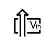
Q.2What function have the sense pins?
This feature moves the effective output voltage regulation point from the output of the unit to the point of connection of the remote sense pins. This feature automatically adjusts the real output voltage in order to compensate for voltage drops in distribution and maintain a regulated voltage at the point of load. If the remote sense feature is not to be used, the sense pins should be connected locally. The +Sense pin should be connected to the +Vout pin at the module and the -Sense pin should be connected to the -Vout pin at the module. Wire between +Sense and +Vout and between -Sense and –Vout as short as possible. Loop wiring should be avoided. The converter might become unstable by noise coming from poor wiring. Please refer to application for further information.
-
Q.3How to learn the product discontinued information?
Through “Products”, you can see “Not Recommended for New Designs(NRND)” and “EOL Products”.
Products listed on NRND (Not Recommended for New Design) list means these models will be gradually discontinued and replaced in the future, and may start the EOL procedure.
Products listed on EOL (END of LIFE) list means there will be no more manufacturing and selling for those. However, the after service will still be carried out.
-
Q.3What function has the trim pin?
The trim pin (if fitted) can be used to trim the regulated output voltage up or down within a limited range. Please refer to the application note for further information.
-
Q.4How to find products you need from CINCON website?
1. Browse by Category
Click “Products” on the website Menu.
Click “product categories” such as DC/DC Converters, AC/DC Power Supply or LED Power
Click “product sub-categories” what you need.
Through wattage and function information, you will find the products you need.
Through Power, Input Voltage, Output Voltage, Features and Dimensions, you will find the product series you need.
Click “product series”, you will find more information by product models.
2. Product Selector
Click “Products” on the website Menu, then Click “Product Search”, or click “SEARCH” icon from the upper of CINCON website.
By choosing product category and electrical characteristic, or enter” Part Number Keyword” related product and specification are shown below.
3. Google Search
If you know the series name, type the “Part Number Keyword” with site:www.cincon.com command, will only search the related product information at www.cincon.com.
For example: type “CHB50 site:www.cincon.com”, will only show the CHB50 related information at www.cincon.com.
-
Q.4What function has the CTRL pin?
The Remote On/Off or Remote or On/Off or On/Off Control pin is commonly used for controlling the power module ON or OFF. Please refer to the application note for further information.
-
Q.5What is positive or negative control pin logic?
Positive control logic means that logic 0 (low) disables the converter and logic 1 (high) enables the converter.
Negative control logic means that logic 0 (low) enables the converter (module ON) and logic 1 (high) disables the converter (module OFF).
Please refer to the datasheets and the application notes for details.
-
Q.6What is the difference between no load input current (quiescent or standby current), off converter input current (shutdown current) and on/off current (control pin current)?
The no load input current is the current drawn by the converter from the supply while it is unloaded (the converter is active and has an output voltage, but no output current), also called quiescent current or standby current.
The off converter input current is the residual current drawn by the converter from the supply when it is disabled by using the control pin, also called shutdown current or shutdown input idle current.
The on/off current is the current drawn by converter through the control pin in order to keep it in the disabled state (enable state for negative logic control), also called control pin current.
-
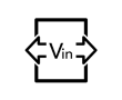
Q.7What is the maximum voltage that control pin could apply?
The maximum voltage that control pin could apply varies from converter series to converter series. Do not connect an unused control pin to +Vin unless the maximum allowed control pin voltage can withstand the voltage stress. Refer to the datasheets and application notes for guidance.
-
Q.8Show DC-DC converter application circuit
1. Applying the reverse polarity output
2. Using a multiple output unit as a single output unit
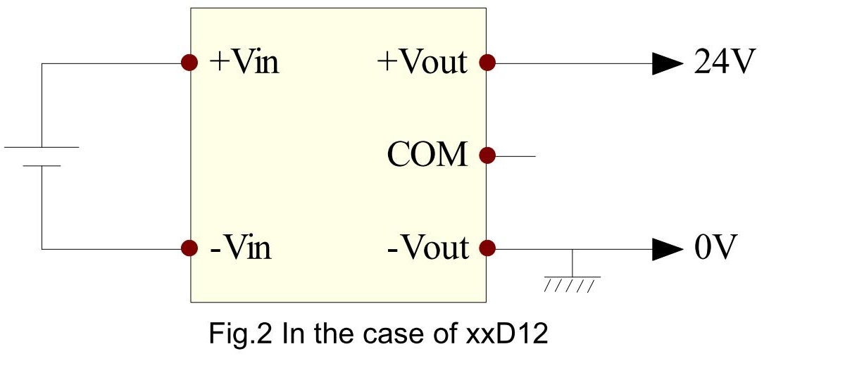
3. Other usage
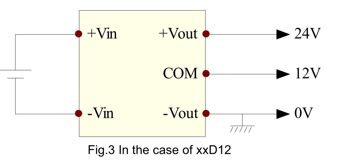
* Currents of 12V and 24V output flow to 0V line. Please make sure that the sum of these values should not be exceeded the rated current of DC-DC converter.
**Please refer to the application note for more application.**
-
Q.9What happens if I use an unbalanced load on a dual output converter?
Some unregulated converters feature power sharing, where all or some of the load can be taken from just one output pin.
Regulated dual output converters regulate the voltage between +Vout and -Vout and allow the common pin to float. (So if a +/-15V is asymmetrically loaded with, say +80%, -20%, then the output voltage difference will stay 30V, but the common pin will drift so that the output voltage will measure +13, -17V, for example). If a balanced output is required with unbalanced load, then use post-regulation to stabilize the outputs.
Please see cross regulation specification in datasheet for detail.
-
Q.10Does rated power change when output voltage adjusted?
If the output voltage is adjusted, the output power and output current must be considered. Always ensure that the output power of the module remains at or below the maximum rated power. Also be aware that if Vo.set is below nominal value, Pout.max will also decrease accordingly because Io.max is an absolute limit. Thus, Pout.max = Vo.set x Io.max is also an absolute limit.
1. TRIM UP, the output voltage exceeds the nominal voltage
Please be aware Maximum output power = Rated output voltage x Rated output current. The power supply is not allowed to be operated in the output power that exceeds the maximum output power because the power supply may get broken by heating the internal components.
ex.)The case that the output voltage of the CHB100W-24S05 is changed to 5.2V
The maximum output current that the power supply is allowed to be operated;
= Maximum output power / Output voltage setting
=100W / 5.2V
=19.23A
2. TRIM DOWN, the output voltage is less than the nominal voltage
The output current must be less than the rated current because the power supply might get broken by heating the internal components.
ex.)The case that the output voltage of the CHB100W-24S05 is changed to 4.8V
Maximum output current = 20A
-
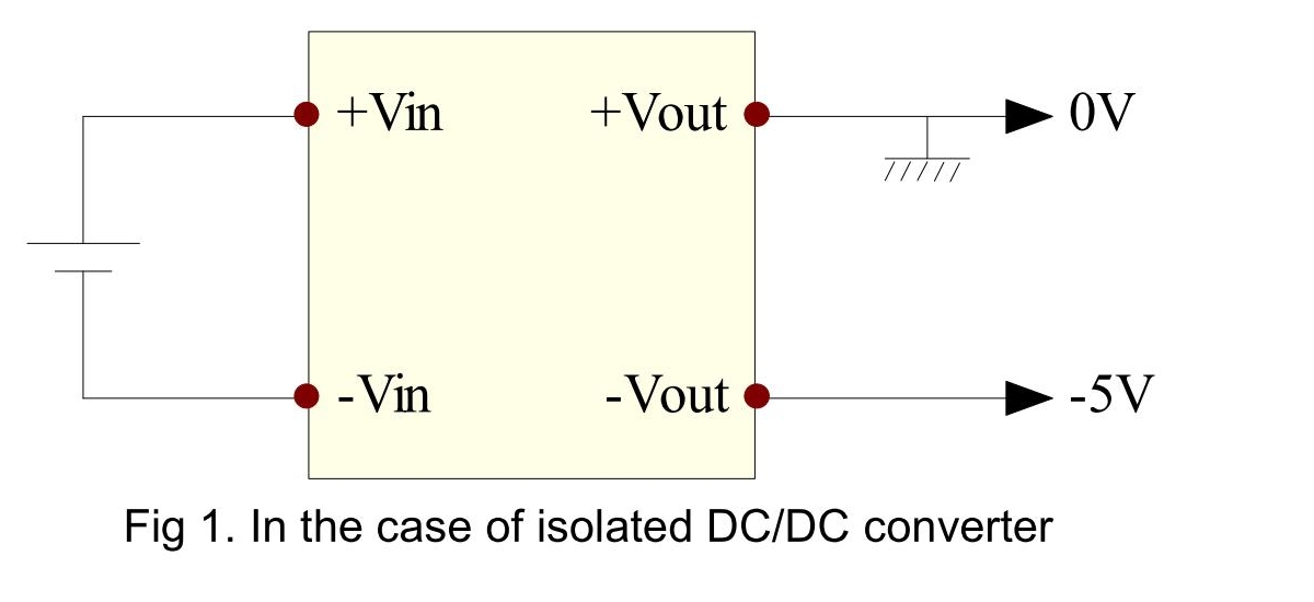
Q.11Does it matter of the input is positive or negative voltage compared to the output voltage?
As an isolated DC/DC converter has no electrical connection between the input and output, it does not matter if +Vin is connected to a positive supply and -Vin is connected to ground or if +Vin is connected to ground and -Vin is connected to a negative supply. This is useful in the telecommunications industry, for example, where a standard -48V supply can be used to generate a +5V output (+Vin = ground, -Vin = - 48V, +Vout = 5V, -Vout = ground).
Please do not apply this to a non-isolated switching regulator.
-
Q.12What happens if I connect the +Vin and -Vin the wrong way around?
Generally, a DC/DC converter has no reverse polarity protection function inside. It will cause converters damaged if connected the wrong way around. If it is possible or likely that the converter could be reverse polarity connected, then a proper circuit must be used to protect the converter (refer to the application notes).
-
Q.13What is the difference between a DC/DC converter with 1:1, 2:1(two-to-one), 4:1(four-toone), 8:1(eighth-to-one) and 12:1(twelve-to-one) input range?
The ratio refers to the input voltage range. For example:
Input Range 1:1 2:1 4:1 8:1 12:1 Nominal Input Voltage 24V 24V 24V 36V 72V Low Line 21.6V(-10%) 18V 9V 9V 14V High Line 26.4V(+10%) 36V 36V 75V 160V -
Q.14What happen if operated out of the input voltage spec?
If a power supply is operated outside the spec of the input voltage range, it may run into problem as the following. Therefore, it is not allowed to be operated outside the spec of the input voltage range.
1. Operated at lower than the spec of the input voltage range
Basically, the power supply can not be operated at lower than the spec of the input voltage range. Even if the power supply work, the power supply may get broken because the input current that is increased may exceed the rated current of internal components.
2. Operated at higher than the spec of the input voltage range
If the power supply is operated at higher than the spec of the input voltage range, it may get broken because the voltage that is applied to some internal components may exceed the rated voltage of them.
-
Q.15How much is the tightening torque?
The recommended tightening torque value for terminal block screws is shown below.
Table 1.1 Recommended tightening torque value
No. Screw size Recommended value [N·m] [kgf·cm] 1 M2.5/M3 0.363 ~ 0.490 3.7 ~ 5.0 2 M4 0.941 ~ 1.250 9.6 ~ 12.8 3 M5 1.860 ~ 2.450 19.0 ~ 25.0